Wedge wire screen filer elements are made of stainless steel wedge wire screen. Filter rating is from 30 to 80 microns. Wedge wire screen is welded onto rods with stainless steel wedge wire at every contact point. They are classified into filer sheet, filter basket and filter elements. They have such characteristics as good strength, high ridity, resistance to abrasion and corosion, even gap, good in filtration and fluidity, easy to clean and back wash.
Stainless Steel Filter Cartridge,Wedge Screen Filter Cartridge Henan Sinofiltec Technology Co.,Ltd , https://www.airfilters.pl
Oil Oval Gear Positive Displacement (PD) Flowmeters
Oval wheel flow-meters(High Viscosity Oval Gear Flowmeters)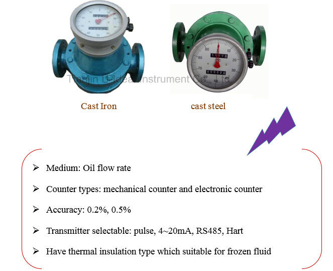
1.     General Description
High accuracy positive displacement flowmeter for wide range of fluids including water, petroleum, solvent. The mechanical counter allows checking of total flowrates in the field. Output furnished flowmeter is also available optionally.
Tianjin U-ideal Instrument oval flowmeter is suitable for viscous oils, ranging from hydraulic to light gear oils, eliminating any problems associated with changes in viscosity during operation. It also provides the advantage of positive displacement technology at a rotameter price. This flowmeter has a cost-effective design allowing for stress-free maintenance. The only wearable components are the oval gears and their axles, allowing the two-step rebuilding process to be easily accomplished in minutes with no necessary recalibration.2.     Structure and Operation Principle
 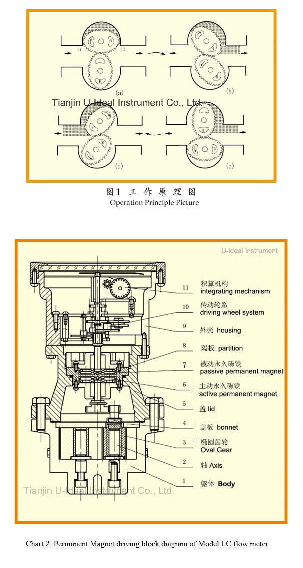
U-ideal Oval meter is generally comprised of a flow transducer and a counter mechanism. The main part of the transducer is a measuring chamber which consists of a pair of oval wheels and a sealing coupling. The counter mechanism contains speed reduction gears, adjusting device, counter, and pulse transmitter etc.
Â
Â
In the measuring chamber, a pair of oval wheels and cover plate makes a crescent shape cavity which is used as a measuring unit. The oval wheels are rotated by the pressure difference in the inlet and outlet of the meter and drive the inlet liquid through the cavity to the outlet, each revolution of the oval wheels displaces fluid four time the volume of the cavity, the total revolutions of the oval wheels and the revolution rate will be
Â
transferred to the mechanical counter, and the total liquid volume and instantaneous flow will be known by the pointer display and the roller integration. The attached signal generator converts the rotary axial angular shift to the pulse signal and then transmits it to the electrical indicator for remote integrated flow and instantaneous flow indication and control.
Â
Â
Chart 2: Permanent Magnet driving block diagram of Model LC flowmeter
Â
Â
Chart 3: PTFE PD meter diaphragm3.     Technical Specification
   Nominal operating pressure ..... 1.6~42MPa
   Norminal diameter:......... 8~300mm
   Counter:............ .... mechanical counter or electronic counter
   High accuracy: ............... ±0.5% RD (Option: ±0.2% RD)
   Viscosity: .................. 0.3~200MPas or 0.3~1000MPas
   Temperature: ............. 0~60 or -20~+300°C (environment: -20~+70°C)
   Material: ............... Cast Iron, Cast steel, SS316 or other material on order
   Pressure drop:............ 0~1000Mpas<80kpa
   Flow range................ See table
 4.     Flow range:                                                unit: m3/h
Type
DN
Viscosity (MPa. s)
Â
<0.3
0.3~0.8
0.8~2
2~200
200~1000
1000~2000
LC-10
10
Â
0.2-0.5
Â
0.08-0.5
  0.08-0.5
0.05-0.5
0.06-0.3
0.03-0.3
0.03-0.2
Flow Range
unit: m3/h
LC-15
15
Â
0.75-1.
Â
0.3-1.5
0.3-1.5
0.15-1.5
0.2-1.0
0.1-1.05
0.07-0.75
LC-20
20
Â
1.5-3
1-3
0.4-3
0.5-3
0.3-3
0.4-2.1
0.2-2.1
0.15-1.5
LC-25
25
4-6
3-6
2-6
0.8-6
1-6
0.6-6
0.8-4.2
0.4-4.2
0.3-3
LC-40
40
9-15
7.5-15
5-15
2-15
2.5-15
1.5-15
2.1-10.5
1.0-10.5
0.7-7.5
LC-50
50
10-24
8-24
8-24
3-24
4.8-24
2.4-24
2.4-16.8
1.6-16.8
1.2-12
LC-B40, 50
40, 50
8-20
6-20
6-20
4-20
4-20
2-20
2.8-14
1.4-14
1.0-10
LC-B65
65
27-40
20-40
15-40
5-40
8-40
4-40
5.6-28
2.8-28
2-20
LC-80
80
40-60
30-60
20-60
8-60
12-60
6-60
8.4-42
4.2-42
3-30
LC-100
100
67-100
50-100
34-100
13.-100
20-100
10-100
14-70
6-70
5-50
LC-150
150
38-120
38-120
40-120
12-120
24--120
12-120
15-100
10-90
16-80
LC-200
200
227-340
170-340
114-340
43-340
56-340
34-340
47.6-238
23.8-238
17-170
LC-250
Â
Â
Â
Â
80~500
150~450
Â
Â
Â
Â
Â
Accuracy
Â
0.5
0.5
0.2
0.5
0.2
0.5
0.2
0.5
0.5
Â
Note
"gal/h" could be special ordered.
Â
2. When the medium measured is corrosive, the maximum flow should be reduce to 2/3 above.
 5.     Installation and usage
1)Â Â Â Â Â Follow the right flow direction on flowmeter body. And make it easy reading.
Chart 4: position of installation
Â
2)Â Â Â Â Â The flowmeter should be installed in the normal temperature place where no harmful gas and strong heat radiation to protect the flowmeter.
3)Â Â Â Â Â The oval gear axis shall be in level position i.e.the dial shall be installed to the vertical position (graduation "0" shall be on the top) to decrease confriction between oval gear and carcase and abrasion of spare parts. To be convenient for reading, the counter can be rotate to 90 degree or 180 degree according to the different installation position.
4)Â Â Â Â Â The pipes shall be completely washed before installation of flowmeter. The filter shall be installed upstream of flowmeter if filter no filter available to avoid impurity to the flowmeter.
5)Â Â Â Â Â
The flowmeter shall be installed at the side of the pump's outlet while the flow regulating valve at the backward position of the flowmeter First open the stop valve at the upper side, then open the flow regulating valve or stop valve slowly at the backward position, it is strictly prohibited to open or close suddenly.
Chart 5: position of installation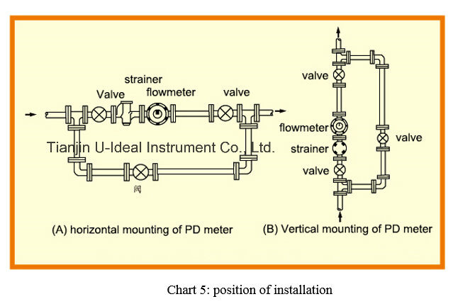
1.     Error Adjustment
Error E=
Â
1)Â Â Â The standard of double layer gear designed is 38/35. If it is found the flowmeter runs fast when checking, it means "+" errors occurred. For example +1.02 -+0.3% ( average error is +0.66%). The error of standard double layer gear 38/35 shall be treated as '0' and adjust 0.66% lower. Referring to the error registration chart, replace the gears with the corresponding double layer. Take the nearest value 0.62%, replace double layer gear 41/38 to decrease error to +0.4%~-0.32% which is within the qualified scope.
2)Â Â Â Precision of flowmeter will be changed owing to gears'abrasion during usage and lead to ultra-error. It can be adjusted up to garde if error range is less than 1 %. For example, if precision of meter declined to + 0.22%Â Â Â Â Â Â 0.64% (average error is - 0.21 %), first check number of teeth of original double gear. If it is 38/35, adjust as the above No.l. If it is 41/38 gear, corresponding error +0.62% shall be treated as 0, raise 0.21% to make error decline 0.21% and change into 0.41%. Referring to the error registration chart, replace 40/37 double layer gear. (Its error is 0.43% and it is most similar to 0.41%). The actual error will decline 0.19% after adjustment. Precision of meter is +0.41--0.45% within qualified scope.
3)Â Â Â Means to verify and adjust Grade 0.2 oval gear flowmeter is same as above item 1, item2.
4)   Take off  housing ( in chart 2 and chart 3 ) first and loose axle sleeve at the back of it (See chart 6, same below ) and nuts ,, replace and adjust gear, then turn adjusting board to make adjusting gear and driving gear,to joggle correctly, tighten axle sleeve and nuts.
Â
Error Adjustment Table
Error adjustment % under DN40
Adjustment gear set
Â
Error adjustment % DN50~200
Adjustment gear set
Z1
Z2
Z1
Z2
When the indicated flow rate is smaller than the actual value, Z1, Z2 can be selected from bottom to top. →
â†When the indicated value is larger than the actual value, Z1, Z2 can be selected from top to bottom.
3.27
37
33
When the indicated flow rate is smaller than the actual value, Z1, Z2 can be selected from bottom to top→.
â†When the indicated value is larger than the actual value, Z1, Z2 can be selected from top to bottom.
4.21
33
30
2.94
38
34
3.90
34
31
2.63
39
35
3.62
35
32
2.34
40
36
3.35
36
33
2.06
41
37
3.10
37
34
1.80
42
38
2.86
38
35
1.55
43
39
2.63
39
36
1.32
44
40
2.42
40
37
1.09
45
41
2.22
41
38
0.88
46
42
2.02
42
39
0.74
35
32
1.84
43
40
0.48
36
33
1.75
29
27
0.23
37
34
1.67
44
41
0.00
38
35
1.50
30
28
0.22
39
36
1.35
46
43
0.43
40
37
1.27
31
29
0.63
41
38
1.05
32
30
0.81
42
39
0.85
33
31
0.99
43
40
0.66
34
32
1.16
44
41
0.48
35
33
1.32
45
42
0.31
36
34
1.47
46
43
0.15
37
35
1.54
31
29
0.00
38
36
1.75
32
30
0.14
39
37
1.95
33
31
0.28
40
38
2.14
34
32
0.40
41
39
2.31
35
33
0.53
42
40
2.489
36
34
0.64
43
41
2.63
37
35
0.75
44
42
2.78
38
36
0.86
45
43
2.92
39
37
0.96
46
44
3.05
40
38
1.14
24
23
Â
Â
Â
Â
 1.32
25
24
1.47
26
25
1.62
27
26
1.75
28
27
1.88
29
28
2.00
30
29
2.11
31
30
2.21
32
31
2.30
33
32
2.39
34
33
2.48
35
34
2.63
37
38
2.77
39
38
2.89
 41
40
3.01
43
42
3.16
46
45
Diesel oval gear flow meter, Digital oval gear flow meter( Pd flowmeter; Gear flow meters) Oval gear flowmeter with LCD, digital oval gear flowmeter, positive displacement flowmeter have 4~ 20mA output and reset function, oval gear flowmeter can display the rate and total flow...
U-ideal instrument supply various positive displacement flow meter for liquid, diesel oil, natural gas. With high accuracy.
U-ideal instruments provides 6 measuring principles such as:
Coriolis Mass Flow Meters
Turbine Flow Meters
Micro Flow Meters
Helical Flow Meters
Gear Flow Meters
Thermal Mass Meters
Turbidity Meters
Worldwide markets include various industrial sectors such as automotive, polyurethane, steel, food, chemical and petroleum as well pharmaceutical industries. The companies in these sectors employ the flow meters on their test benches, filling lines, batching and paint-spraying systems.
More than 40 years of experience in flow metering equipment combined with innovative and customised product development enable KEM Kuppers to be your competent partner for various matters of flow measurement
Mass Flow Meter
Mass Flow Meter for all kinds of fluids. Measuring ranges from 4.5 kg/h up to 60, 000 kg/h and pressures up to 350 bar.
Coriolis Mass Flow Meter
Tricor Mass Flow Meter (Coming up)
Gear Flow Meter
PD Flow meters for all paints, paint dispense control devices, fuel consumption control devices, polyol and isocyanate, coating and cavity wax, glue, PVC, filled and abrasive fluids, pd meters for hydraulic oil Measuring ranges from 0.005 up to 1, 000 l/min.
Typical viscosity range from 0, 5-25.000 mm2/s
Gear Flow Meters in Standard Design
Gear Flow Meters in Cartridge Design
Gear Flow Meter with Ball Bearings
Aluminium Gear Flow Meters
Dispense Control Device
Gear Flow Meters for High Pressure Applications
Gear Flow Meters for Test Rigs, Diesel, Chemical Injection
Turbine Flow Meter
Flow measurement of fuels, light fuel oil, thermal oil, solvents, tap and demineralised water. Special turbine meters for refrigerants.
Measuring ranges from 0.03 up to 48, 000 l/min.
Typcal viscosity range from 0.5-100 mm2/s
Turbine Flow Meters -General Overview / Measuring Principle
Turbine Flow Meter with Flange Ends
Turbine Flow Meters with Female Inch Threads
Turbine Flow Meters with Ermeto Fittings
Turbine Flow Meters for Pharmaceutical Applications
Turbine Flow Meter for Solvents and DI-Water
Turbine Flow Meters for High Pressure Applications
Turbine Flow Meters for Temperature Control Units
Aluminium Turbine Flow Meters
Helical Flow Meter
Flow meters for epoxy resins, PVC and underbody sealants, anti-flutter materials, adhesives, polyurethane, polymers, sealants, petrochemicals and thixotropical fluids, grease, oil, glues, heavy fuel oil.
Measuring ranges from 0.01-400 l/min.
Typical viscosity range from 1-1, 000, 000 mm2/s
Helical Flow Meters in Standard Design
Helical Flow Meter with Integral Double Pickup (-Compact)
Helical Flow Meters with Ball Bearings
Micro Flow Meter
Flow measurement of additives, pharmaceuticals, aromatic substances/perfumes, liquefied gases, fluid food, demineralised water, 2- and 3-component applications
Measuring range from 0.005 up to 0.25 l/min.
Typical viscosity range from 0.5-6 mm2/s
Micro Flow Meter
Turbidity Meter
The Turbidity sensor serves the optimizing of industrial production processes in the food industry, chemistry, pharmacy
Turbidity Meter
Â
Oval Gear Flowmeter
Precision:<±0.5%
 Material: cast steel/stainless steel/cast iron
 Optional: Pulse output; reset function
 NP:1.6Mpa/2.5Mpa/4Mpa
Temperature:-40~ +160 ºC
Â
Rotary Piston Flowmeter
 Wide Flux---:1L/H-16000L/H
 Optimized structure---: No flow adjustment is required.
 Measuring Medium---: Petro, Diesel oil, Diesel oil, Distilled water, Juice, Chemical reagent etc.
Safety---:Flow through the meter continues even when piston was stuck by    impurity.
 High precision: Up to 0.3%
Self-lubricant, high precision, high reliability, low noise, smooth running, easy maintenance
Â
Wet-test(drum-type) gas meter
 Applications & User Benefits
 Wet-test (drum-type) gas flow meters are used universally to
measure and record gas volume and gas flow rate for many industrial,
 petroleum and chemical processes; environmental; pilot plant or
 test; controlled chamber; laboratory and research applications.
 Wet-test meters consistently provide the highest accuracy and
 precision even at the lowest gas flows with inert or the most
aggressive gases
Â
Mechanical meter
 3-wheel mechanical diesel flowmeter
 4-wheel mechanical diesel flowmeter
4-wheel mechanical fuel flowmeter
Â
Liquid roots flow meter
 Accuracy: ±0.5%;±0.2%
 Material : cast steel/stainless steel/cast iron
 Optional: pulse output; reset function
 Normal pressure:1.6Mpa/0.6Mpa
Temperature:-10~ +60 ºC
 Rotors never touch each other and therefore are not subject to wear.
 More over double case construction allows to maintain the measuring unit
Without removing the entire PD flowmeter form the line.
Â
UE-F Double rotator flow meter
 Applies to low viscosity oil, light oil, heavy oil, crude oil with sand and water, liquid from low viscosity to high viscosity.
 Max. flow is 2 times larger than normal flowmeter.
 Long life, high accuracy and reliability.
 Minimal pressure loss.
 1000 meters of cable for long distance output. pulse output N=0.1L(a pulse for 1N), for direct connection with computer networking.
An explosion of the Ia II CT6(intrinsic safety type); flameproof d II BT6(flameproof); protection IP56.
Application Wedge wire screen filter elements are used in sieving of petroleum, chemical industy, pharmaceutics, food and beverage, metalurgy and coal, also can be used in fitration of water treatment.
Wedge wire is a welded steel structure, mainly used for filtration, separation and retention media.
It consists of surface profiles, usually V-shaped, that are resistance welded onto support profiles. The distance between the surface profiles is controlled very accurately, as it forms the slot through which the filtrate flows.


Model NO.: LC-A
Measuring Media: Liquid
Measuring Principle: Mechanics
Measurement Object: Closed Pipeline
Certification: DIN, GB, CE, ISO
Counter: Mechanical Type and Electrical Type
Zero Function: Can Set Back to Zero
Material: Cast Iron, Cast Steel, Stainless Steel
Medium: High Viscosity Fluid Like Diesel Oil
Signal: 4~20mA, Hart, RS485 Optional(Electric Counter Only
Trademark: U-ideal
Specification: ISO
Origin: China
HS Code: 90261000
LC OVAL GEAR FLOWMETER- Mechanical fuel flow meter