aluminum paste, coating Jiangsu Jiali New Material Technology Co., Ltd. , https://www.jlmaterial.com
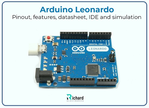
The Arduino Leonardo is a highly versatile and powerful microcontroller board, known for its capability to emulate a mouse or keyboard without requiring additional libraries. This board consists of 20 digital I/O pins, of which seven support PWM outputs, and 12 analog input pins. Additionally, it provides UART, SPI, and I2C communication support. Let's delve into its history, pin layout, technical specifications, features, integrated development environment (IDE), and simulation capabilities.
### History of Arduino Leonardo:
- **2012:** The Arduino Leonardo was introduced to the Arduino series, expanding the range of microcontroller boards available.
- It is based on the ATmega32U4 microcontroller, which includes native USB support.
- In the Arduino lineup, the Leonardo was the first board to have native USB communication without needing an additional USB-to-serial converter chip.
- Designed for advanced projects that require direct interaction with computers via USB ports.
- Fully supported by the Arduino IDE, making programming straightforward.
- Features USB HID capabilities, which set it apart from previous Arduino models.
- Due to its unique features and adaptability, it is commonly used in professional prototyping and educational settings.
### Pin Layout of Arduino Leonardo:
The pin layout of the Arduino Leonardo is critical for understanding how to effectively use the board. Here's a detailed overview:
#### Digital Pins:
- **Pins 0-13:** These are general-purpose digital I/O pins. Pins 0 and 1 are specifically used for serial communication (RX and TX). The remaining pins are used for input or output operations.
- **PWM Outputs:** Pulse Width Modulation (PWM) is supported on digital pins 3, 5, 6, 9, 10, and 11.
A concise breakdown of the digital pins in table format:
| Number of Pins | Type of Pin | Name of Pins/ Protocol | Details |
|----------------|---------------------|------------------------|-------------------------------------------------------------------------|
| D0 | Serial or Digital I/O | RX (UART) | Used for serial communication receive signals (UART) |
| D1 | Serial or Digital I/O | TX (UART) | Used for serial communication transmit signals (UART) |
| D2 | Interrupt or Digital I/O | Digital pin | Used for INT2 (External interrupt) or digital output/input |
| D3 | Interrupt, Digital I/O or PWM | PWM pins | Used for INT3 (External interrupt) or pulse width modulation output |
And so on, continuing with each pin and its respective functions.
#### Power Pins:
- **GND:** Ground pins are essential for completing circuits.
- **5V:** Provides regulated 5V power supply, either from USB or external sources.
- **RESET:** Resets the microcontroller board.
- **VIN:** Input voltage ranging from 7V to 12V.
- **AREF:** Analog reference pin for setting reference voltages.
- **3.3V:** Supplies regulated 3.3V power.
#### Specific Pins:
- **Interrupt Pin:** Used for external interrupts.
- **Pin 13:** Built-in LED.
- **SPI:** Used for SPI communication, found on ICSP headers.
- **I2C Pins:** Data line (SDA) and clock line (SCL).
### Technical Specifications:
The Arduino Leonardo datasheet contains vital technical details about the board. Some key features include:
- Microcontroller: ATmega32U4
- Flash Memory: 32 KB (4 KB used for bootloader)
- Operating Voltage: 5V
- Weight: 20 grams
- SRAM: 2.5 KB
- Length: 68.6 mm
- Digital I/O Pins: 20 pins used for general-purpose applications
- Width: 53.3 mm
- Input Voltage: 7V - 12V
- PWM Pins: 7 out of 20 digital I/O pins support PWM
- EEPROM: 1 KB
- Analog Input Pins: 12 pins used for analog input
- LED Pin: Pin 13 is used for the built-in LED
To access the full datasheet, click [here](#).
This board is not only a great tool for hobbyists but also widely utilized in professional prototyping and educational environments due to its robust capabilities and ease of use.