Non-Explosion Proof Type Pyrometer
This classification includes pyrometers designed for blast furnace have not equipped with explosion proof instrument. If user need explosion proof, we could add explosion proof device.
Conditions in furnace are always tough alone with high temperature and high pressure. Limited to the requirements of operation environment and instrument`s structure, thermocouple thermometry would result in inaccurate measurement and lag reaction when works in harsh condition such as frequently temperature changes, large pressure fluctuations and event in vibration.
Since a thermocouple works at the high temperature ( usually 1200 ℃ ~ 1300 ℃) in furnace for long term, the thermocouple junction box also works at high temperature between 100 ℃ to 120 ℃, which will dramatically reduce instrument`s service life to a range from few weeks to few months. It will increases use-cost and maintenance workload.
In order to overcome above shortcomings, our company has designed and produced a serials of specialized infrared temperature measure device to ensure our infrared temperature measuring system works reliably in complex environment.
Non-Explosion Proof Type Pyrometer,Non Explosion Proof Pyrometer,Furnace Use Pyrometer,Pyrometer For Industry Stove Changzhou Sijie Optoelectronics Technology Co.,Ltd. , https://www.sjinfrared.com
In Part 3, we will explore the differences in structure and rotation principles of brushless motors, comparing them to brushed DC motors and AC motors.
Below is a visual representation of the brushless motor's structure and operational principles:
Brushless motors maintain the excellent controllability of DC motors while replacing their brushes and commutators with electronic components.
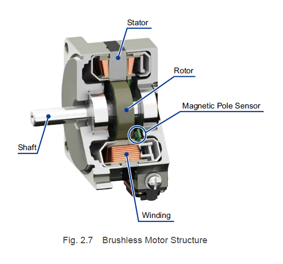
**2.2.1 Brushless Motor Structure**
The rotor contains permanent magnets, and the stator contains windings, reversing the positions of the stator and rotor in DC motors. With brushed DC motors, current is supplied to the windings via the commutator and brushes, causing rotation. As the motor rotates, the next set of commutator and brush are energized, directing current flow into different windings and maintaining rotation. Brushless motors achieve commutation without using brushes or commutators. Instead, they rely on magnetic pole sensors (like hall elements or hall effect ICs) to detect the magnetic pole positions of the permanent magnets and drivers to direct current flow through the windings based on these detections.
**2.2.2 Brushless Motor Rotation Principles**
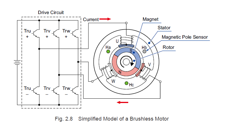
To explain the rotation principles of brushless motors, we'll use the simplified three-phase, 2-pole model shown in Figure 2.8.
With rotor magnets, both the north and south poles have a magnetic pole angle of 180°. Magnetic pole sensors Ha, Hb, and Hc are spaced 120° apart and detect the north pole of the rotor magnets, outputting a signal. The phase-U coil, phase-V coil, and phase-W coil in the stator are spaced 120° and offset from the magnetic pole sensors by 60°.
For each of the stator’s phase windings, a south pole is generated on the inner diameter side when current flows from the drive circuit to the motor. When current flows in the opposite direction, a north pole is generated. Figure 2.8 shows the state when current flows from phase-U to phase-V.
For the explanation of the motor rotation principles, let's use the rotation sequence shown in Figure 2.9 and assume that the orientation of the rotor magnets shown in Figure 2.8 is the initial point (0°).
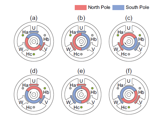

1. In interval (a), magnetic pole sensors Ha and Hc detect the north pole and output a signal. If transistors Tru+ and Trv= are turned ON, current flows from the phase-U coil to the phase-V coil in the stator. Phase-V becomes magnetized as a north pole (excitation), attracting the south pole and repelling the north pole in the rotor magnets. Phase-U becomes magnetized as a south pole (excitation) and repels the south pole in the rotor magnets. This causes the rotor to rotate clockwise.
2. In interval (b), which is past 60°, only magnetic pole sensor Ha detects the north pole and outputs a signal. If transistors Tru+ and Trw- are turned ON, current flows from the phase-U coil to the phase-W coil in the stator. Phase-U maintains excitation, attracting the north pole and repelling the south pole in the rotor magnets. Phase-W is excited as a north pole and repels the north pole in the rotor magnets. This causes the rotor to rotate clockwise.
3. For each 60° of rotation, the combination of ON and OFF states for magnetic pole sensors Ha, Hb, and Hc changes. For a single rotation of the motor, there are six different magnetic pole sensor output combinations, represented by (a) through (f). Through the sequential switching of a determined set of excited phases for each pattern, a rotating magnetic field is continuously generated.
Additionally, by changing the way current flows through the coil for each of the output combinations for magnetic pole sensors Ha, Hb, and Hc, the motor rotation direction can be reversed.
For example, if transistors Trv+ and Tru- are turned ON when only magnetic pole sensor Ha detects a north pole and outputs a signal at interval (b) noted above, current flows from the phase-V coil to the phase-U coil in the stator. At this time, phase-U becomes excited as a north pole, attracting the south pole and repelling the north pole in the rotor magnets. Phase-V becomes excited as a south pole and repels the south pole in the rotor magnets. This causes the rotor to rotate counter-clockwise.
In summary, brushless motors rotate by directing current flow through the phase coils according to the magnetic pole sensor output signals. The detection of the sensor output signals, as well as the automatic switching of transistors, are handled by a "drive circuit," which is sometimes referred to as a "driver" or "drive."
**TIP: Brushless Motor Currents**
Direct current is applied to the drive circuits of brushless motors, but alternating current flows through the motor. For this reason, brushless motors are sometimes called AC synchronous motors.
**2.2.3 Brushless Motor Characteristics**
As explained in "2.2.1 Brushless Motor Structure," the stator and rotor positions in brushless motors are the opposite of those in DC motors. For this reason, the fundamental speed-torque characteristics for brushless motors exhibit the same sloping characteristics as brushed DC motors, as shown in Figure 2.10, and the motor rotates at a rotation speed that matches the load torque.
If the speed slows down, the torque generated by the motor increases, and a current proportional to the torque flows. If a large current flows, the magnetic force of the permanent magnet in the motor may decrease (demagnetization), and the windings may overheat and experience burnout. In addition, the output element and converter on the drive circuit must be able to handle large currents, which causes the drive circuit to be large and expensive.
If the speed increases, the torque generated by the motor decreases, and the load torque required for driving decreases, making it unsuitable for use. Operating it at a higher speed increases the noise emitted by the gearhead combined with the motor, and it also causes insufficient gearhead lubrication, which affects the lifespan.
For the above reasons, with brushless motors, the drive circuit limits the maximum current that flows through the motor and the maximum rotation speed. Thus, the speed-torque characteristics printed in Oriental Motor's product catalog are similar to Figure 2.11.
**TIP: Rotor Magnet Demagnetization**
Permanent magnets are magnetized by applying a strong magnetic field to magnet materials. Conversely, causing excessive current to flow through a motor causes the stator to generate a diamagnetic field, which decreases the magnetic force of the rotor magnets. This is called demagnetization.
Oriental Motor's motor and driver systems are designed to prevent demagnetization at the current at which the maximum instantaneous torque is generated.
**2.2.4 Brushless Motor Features**
The features of brushless motors are listed below.
**Compared to DC Motors**
- The speed-torque characteristics have the same sloping characteristics as brushed DC motors and have excellent controllability.
- Because there are no brushes or commutator, there is no need to clean the abrasion powder, replace the brushes, or perform other periodic maintenance, giving them a longer life span.
- Since there are no brushes or commutator, there is no electronic noise due to arcs. Switching noise is generated.
- No mechanical acoustic noise (brushes) is generated.
- Magnetic pole sensors and drivers are needed for operation.
- Since the motor rotation speed is detected from the magnetic pole sensor output and feedback control is performed, there is high speed accuracy.
- Because there is feedback control, abnormal behavior can be detected during operation.
**Compared to Inverter Controlled Motors and AC Speed Control Motors**
- Since the torque is flat from low speed to high speed, the speed ratio is large for all practical purposes.
- If compared at the same output power, the brushless motor is compact and more efficient.
- Can be used with a DC power supply.
- Since the motor rotation speed is detected from the magnetic pole sensor output and feedback control is performed, there is high speed accuracy.
- Because there is feedback control, abnormal behavior can be detected during operation.
Since brushed DC motors are inexpensive, they are used for various applications where required life span is relatively short. However, for general industrial use, not only are there problems with the life span and maintainability, but there is also a need for a high level of reliability in terms of speed accuracy during operation, malfunction detection, and so on, which has led to increasing popularity of brushless motors. In addition, since the motors are compact, have high output power, and are highly efficient, they are used in devices that need to be compact and lightweight, as well as for battery-powered devices.
If you're interested in learning more, feel free to check out our resources below:
[HubSpot Call-to-Action]
Subscribe (top right corner) to receive monthly updates!
This article was written to provide a comprehensive understanding of brushless motors, their structure, and their unique advantages over other types of motors. Let me know if you have any questions!