"Trigger" is definitely called the concept of a digital oscilloscope soul. If there is no suitable trigger condition, waveform observations can not be discussed. Although many engineers are familiar with the trigger function, they only know what they are. How to understand the trigger in depth? This ZDS oscilloscope R&D notes is here for everyone to share.
When using the oscilloscope, we must first obtain a stable trigger waveform, so as to ensure the reliability of advanced functions such as subsequent measurement and decoding. The triggering function of digital oscilloscopes is now more and more powerful, from regular triggers, to protocol triggers, to template triggers, more and more powerful. However, in the basic trigger settings, the role of some small details can not be ignored, after a flexible grasp, the use of oscilloscopes will also be of great benefit. In the following, we will analyze and communicate the trigger function, trigger filtering in the settings, trigger sensitivity and hold-off time.
First, the principle of oscilloscope trigger
Oscilloscope trigger system and sampling system are important parts of the oscilloscope. The sampling system is responsible for digitizing the analog signal, but the signal is coming from the source continuously. Which part of the signal is displayed on the interface of the oscilloscope?
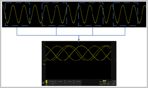
If the oscilloscope does not trigger the system, the sampled waveforms are superimposed at regular intervals or at random times. Due to the uncertainty and irregularity of the sampling position, the very confusing waveform display in Figure 1 will appear. It's like scrolling back and forth.
Figure 1 does not trigger the system's waveform sampling
This confusing phenomenon is consistent with the phenomenon of unstable trigger on the oscilloscope. The following dynamic diagram shows:
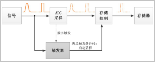
This depends on the trigger system. The principle of triggering is to monitor the signal flow all the time. If it is found that the signal satisfies the set trigger condition, the trigger records the signal that satisfies the condition and starts sampling; after the data is collected, the controller processes and displays the signal. Specifically as shown in Figure 2.
Figure 2 Triggering process
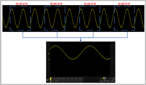
One of the key factors of the oscilloscope's triggering condition is the trigger level. In most cases, the trigger level uses a DC level as a reference. When the voltage of the signal exceeds the DC level, the starting point of the sampling waveform is used. Because the position of the initial sampling is regular, the multi-sampled waveforms appear to be a stable waveform after being superimposed. As shown in Figure 3:
Figure 3 Stable triggered waveform sampling
The triggering function of the oscilloscope can make the waveform stable on the one hand, and the waveform can no longer be shaken from side to side; on the one hand, the time for debugging by the user can be shortened, and only the signal meeting the trigger condition will be captured and displayed.
Dynamically adjust the trigger level of the oscilloscope to observe the dynamic change of the position of the stable trigger of the waveform, as shown in the following dynamic diagram.
Second, trigger filtering
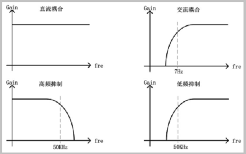
In the commonly used settings, generally set the trigger type, trigger voltage, the waveform can be displayed stably. However, for a relatively noisy signal, the trigger is unstable and the upper and lower edges can be triggered. This is because the presence of signal glitches interferes with the trigger system's judgment of the trigger conditions, causing false triggering. At this point in the trigger settings, select the trigger coupling operation. The usual coupling is as follows:
DC coupling : no processing is allowed to allow the DC AC signal to enter the trigger path;
AC coupling: high-pass filtering, cut-off frequency of about 7Hz;
Low-frequency suppression : high-pass filtering, cut-off frequency of about 50KHz;
High Frequency Suppression : Low-pass filtering with a cut-off frequency of approximately 50KHz.
Specifically as shown in Figure 4:
Figure 4 various filter performance
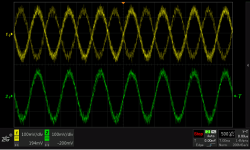
Triggered coupling is actually a low-pass or high-pass filtering of the trigger signal. Therefore, the “high frequency suppression†coupling can be added to the signal with large noise, and the high frequency part can be filtered out, making the waveform triggering stable as shown in FIG. 5 .
Figure 5 CH1 does not turn on the high-frequency suppression trigger instability, CH2 turns on the high-frequency suppression
Third, trigger the role of suppression
In the trigger settings, the trigger triggering function is generally ignored. By definition, holdoff is the minimum interval between two triggers defined.
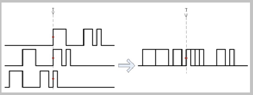
When the oscilloscope triggers once, it will enter the trigger holdoff count. During this time, the trigger function will be suppressed. Even if the signal meets the trigger condition, the system will not be marked as the trigger point. The setting of holdoff is very easy to use for the signal capture of the occasional polygonal edges, making the original image unstable waveform immediately clear. If the trigger holdoff time is set incorrectly, the oscilloscope will use the signals of different edges as the trigger points to overlap, causing the waveform display to be abnormal, as shown in Figure 6. The setting of the holdoff time is shown in Figure 7.
Figure 6 Waveform display is abnormal due to incorrect holdoff time setting
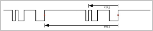
Figure 7 The holdoff time should be between Tmax and Tmin
Fourth, the role of trigger sensitivity
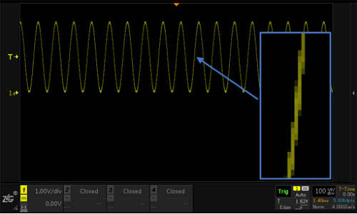
The trigger level is just a reference voltage, and the actual waveform has jitter at the edges. As shown in Figure 8, the waveform has very little interference, but the rising edge still has jaggies. When the noise is large, the jitter will be More violent. If you want to stabilize the rising edge of the trigger waveform, you need to use hysteresis comparisons above and below the trigger level to filter waveform jitter and glitches near the trigger level. This hysteresis range is the trigger sensitivity.
Figure 8 Jitter and Glitches on Trigger Edges
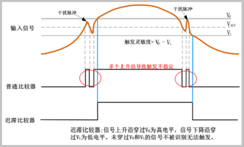
The sensitivity of the trigger signal recognition is shown in Figure 9. When measuring small signals, a higher trigger sensitivity is needed to enable stable signal triggering. This can be done by adjusting the value of the trigger sensitivity to zero or to 0; in the waveform noise When it is larger, the large trigger sensitivity needs to be properly adjusted to effectively filter the noise that may be superimposed on the trigger signal, thus preventing false triggering, as shown in FIG. 10 .
Figure 9 Hysteresis comparator
Figure 10 Effect of sensitivity on signal triggering
When using a ZDS2000/3000/4000 series oscilloscope to measure a signal with a small amplitude, since the oscilloscope default is 0.3div, the oscilloscope is in the 2mv/div~5mv/div range, the trigger sensitivity defaults to 1.0div, because the small signal under the interference Large, can play a role in anti-jamming, and in the 10mv/div~10v/div gear, the default trigger sensitivity is 0.3div, so when measuring the small-signal use hour base gear, it needs manual adjustment, which will trigger the sensitivity of The value is lowered between 0~0.3div.
Summary: Triggering is a very objective operation, which means that you need to know the signal exception before setting the corresponding trigger condition. How can you quickly find anomalies? This should be a prerequisite for a reasonable trigger. ZDS4000 series oscilloscope is based on 512Mpts memory depth, supports 24 kinds of measurement parameters on the same screen display, combined with template trigger, abnormal search, annotation and dual ZOOM and other analysis plug-ins can quickly locate the waveform we are interested in, you can easily in the continuous flow of data Search for abnormal conditions such as dwarf pulses, burrs, and waveform distortion. In addition to 13 conventional triggers, the ZDS4000 also supports 30 protocol triggers and decodes, making debugging no longer stuck in the “pulse†phase, greatly improving the efficiency of the work.
Professional big size CNC EDM Sinker machine manufacturer, the worktable fixed type. We supply best quality CNC EDM Sinker Machine quality and best price and best after service