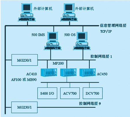
1 Introduction Abb dcs is a distributed control system designed and developed by the Swiss asa brown boveri company (abb for short). It has a wide range of applications and can be applied to discrete manufacturing industries such as machine tools, automobiles, and aircraft manufacturing industries. Small-scale continuous production process industries, such as: petroleum, chemical, thermal power units, steel-making, building materials and other industries. The abb dcs system adopts international standards from hardware design to software design. Abb dcs software programming language ampl (asea master piece language) is a programming model of the control system, this article describes the architecture of abb dcs and its fieldbus network. 2 abb dcs distributed industrial control computer system architecture The abb dcs distributed control system uses advanced microprocessors (33mhz motorola 68020 and 33mhz intel80386, 80486 chip), crt graphics display technology, high-speed secure communication technology and modern control theory to form a field control station (mp200, ac410, Ac450 series and local and remote i/o series), operator station (as500 series), engineer station (master aid series), information management system station (advant station series), computer and network interface station (master gate series), computer Based on network (master bus series) and other computer communication equipments, large-scale intelligent networks with scattered physical locations, decentralized system functions, decentralized control functions, and process control and process decision management with centralized operation and display management. Abb dcs communication network structure is divided into three layers: (network structure shown in Figure 1). Figure 1 Network structure 3 Information Management Network Layer It can be connected to 9 control networks. The network consists of buses of type mb300 with a bus transfer rate of 10 mbps. 4 Control network layer The control network layer consists of 9 buses of type mb300. A control network may include 99 stations (including stations in a local control network). Each mp200/1 or ac450 station in the control network can be connected to a local control network. A local control network can include 9 buses of type mb300. The mb300 is a high-performance, serial, synchronous, half-duplex, high-data-rate, high-speed bus. It adopts ieee 802.2 logical link system (llc) protocol and ieee 802.3 carrier collision multiple access (csma/cd) medium access (mac) protocol, which is an ethernet type LAN, and the bus can carry 45 Nodes. When no repeater is used, the maximum communication node distance is 500m; when using 3 coaxial segments, 4 repeaters, and 2 point-to-point links, the maximum communication node distance is 2500m and the bus transmission rate is 10mbps. The mb300 implements the connection to the host computer through each node and communicates with the plc system such as mp200. It generally follows the 543 rule, which consists of 5 segments, 4 repeater connections, where 3 segments can be attached to the device, it must be noted that only the marked prescription of the cable can be connected via a tranceiver Equipment, different equipment connections and use of different connecting cables, such as to pu510 operation station with tk526 cable, and to control stations use tk576 cable. The tranceiver can only be installed on the 2.5 meter mark on the trunk cable section. The distance between the tranceiver on the coaxial cable section between the two cable connectors should be an integral multiple of 25 meters. The connection method is shown in Figure 2: Figure 2 mb300 network connection diagram T1 and t2 are terminating resistors. As long as one end is grounded, the terminating resistance is 50 ohms. The mb300 bus is a coaxial cable. The specifics are divided into thick cable, thin cable, and optical cable. Their roles are different. When laying coaxial cable, pay attention to it. Separation from other signal cables, such as 30 cm from the signal cable, 50 cm from the 380 v low voltage cable, and 5 m from the high voltage cable. Mb300 bus use cs513 interface card, the above three dial switch s1, s2, s3 were used for the network number, node number, protocol number settings, which s1 lower four bits used to set the choice of master/slave station, The upper four bits are used to set the protocol number, s2 is used to set the node number, and s3 is used to set the network number. When you need to modify or find out the cause of the fault through the fault information, you can enter the engineer station to modify the data or know the fault of the mb300 bus through the fault code. Understand the communication factors that affect the mb300 and analyze them one by one. 5 Fieldbus network layer 5.1 mfb (master field bus) bus The mfb bus belongs to the field LAN bus, which is connected between the mp200, mp90, s400i/o, opc (small control station) and the drive system. Mfb communication bus using coaxial cable, twisted pair, it connects ci520 / ci525 / ci526 communication interface module and dstc452 modem, each twisted pair of wire ends must be isolated, one of the end of the shield must be grounded, mfb communication The rate is 375kb/s, its resistance is 75 ohms, its hardware disposition chart is shown as in Fig. 3. The relevant system information of mfb is obtained from the engineer station. The general sequence is time, information model, code, task number, sequence number, and data. It mainly has the following states. Code 20: cpu communication interface loses contact Code 21: Fatal hardware failure Code 39: device/station ok Code 72 :device/station address ok Code 120: Process Failure Code -1: Execution Error Code - 4: System error Code - 5: Small System Site Error Code - 6: Communication failure Code - 9: Catastrophic bus failure Code -10: Redundant cable interruption Figure 3 hardware configuration 5.2 af100 (advant field)/mb90 (master bus) bus The purpose of af100/mb90 is to provide communication between multiple apc sites or between apc site and abb industrial system equipment. The mb90 supports two different types of communication, data processing and information transmission. The data set is dynamic data. To monitor and control a process, this process is service information used as a parameterization method, program installation, diagnosis. Af100/mb90 is a high-performance regional bus that can connect up to 79 apc sites. The mb90 can be up to 300 meters long, and if equipped with appropriate signal cables and signal repeaters, and long range configurations are available between individual drives, up to 2000 meters. Technical characteristics of the bus (1) Communication speed 1.5mbit/s (2) Attenuation bus length <300m, propagation delay <2000m (3) Telegram length 2, 4, 6, 8, 32 bytes of user data. (4) Identification code (telegraph code) range 1...4000 (5) Cycle time 2, 4, 8, 16, 32, 64, 128...2048 or 4096 ms The af100/mb90 relies on a centralized bus manager. The bus manager functions are more complex and require more. For example, the apc site cannot be used as a bus manager. They do not include the functions of the bus manager. To make it possible to communicate between apc through af100/mb90, each solution (independent and embedded) can be used to schedule the af100/mb90 bus masters. When apc starts executing their applications, the bus master must be Operable, otherwise, when the locally configured data set is not confirmed by the bus manager within the specified time limit, the data set function block within the apc branch will enter an error state. If the system only has apc sites and no masterpiece is connected to the mb90 or ac450 and af100, a separate bus manager should be installed. The communication between abb dcs and the drive system (eg acv700/dcv700) is based on the drrtra (drive transmit) and drrec (drive reciver) elements shown in Figure 4. Figure 4 Communication Elements The drrtra (drive transmit) element is used to pass the data set given to the abb drive controller and the selection of the control word and command word signal for selecting the drive signal is given in the application drive software description. The drrtr element can generate different types of cycle information supported by the drive communication protocol. The destination of the transmitted signal is selected by the drive signal. The drrtr element can also write the parameter. During the normal phase, the overload of the drrtr can be detected. The drrec (drive reciver) element is used to receive signals and control word values ​​from the abb drive controller. These signal definitions are given in the application drive software instructions. The drrec element is only the cycle information supported by the drive connection protocol. The receive data source is selected by the element input parameters to determine the drive signal and the signal index. The drrec element is also able to access parameters, and an overload of drrec during the configuration phase can be detected. 6 Conclusion The interconnection of the information station, operator station, mb300 bus, af100 (mb90) bus and control station is the specific abb network control system. Since the system was put into operation, the work has been stable and reliable, and the field wiring of the original control system has been greatly reduced. It increases the stability and reliability of the system and is worth promoting. Surface acoustic wave touch screen Surface acoustic wave, a kind of ultrasonic wave, a mechanical energy wave that propagates on the surface of a medium (such as a rigid material such as glass or metal). Through the wedge-shaped triangular base (according to the strict design of the wavelength of the surface wave), it is possible to achieve a directional, small-angle surface acoustic wave energy emission. Surface acoustic wave performance is stable, easy to analyze, and has very sharp frequency characteristics in the process of shear wave transmission. In recent years, the application of non-destructive testing, imaging and denoising has developed rapidly, surface acoustic wave related theoretical research, semiconductor materials, sound Lead materials, detection technologies and other technologies are already quite mature. The touch screen portion of the surface acoustic wave touch screen may be a flat, spherical, or cylindrical glass plate mounted in front of a crt, led, lcd, or plasma display screen. The vertical and horizontal ultrasonic transmission transducers are fixed at the upper left corner and the lower right corner of the glass panel, and two corresponding ultrasonic transducers are fixed at the upper right corner. The four perimeters of the glass screen are engraved with 45° angles with very precise reflections from sparse to close spacing. Anhui Tiankang is China's largest production base for temperature meters. Its product categories include: thermal resistance, thermocouples, bimetal thermometers, pressure transmitters for pressure gauges, integrated temperature transmitters, paperless recorders, etc. product. Product cables are: power cables, control cables, fire-resistant cable computer cables, fiber optic cable, data cables, thermocouple compensation wire, and other products. Canvas Tarp Lowes,Waterproof Canvas Tarpaulin,Large Waterproof Tarp,Waterproof Tarp Bunnings Shandong Lufan Technical Textiles Co.,LTD , https://www.lufantarps.com